
3D floor plan rendering: a practical guide for architecture firms
Turning a floor plate into a presentable 3D isometric view used to mean a modelling task for someone on your team. This guide covers how the process works today, where AI-only tools break, and what to check before you put a render in front of a client.
What 3D floor plan rendering actually is
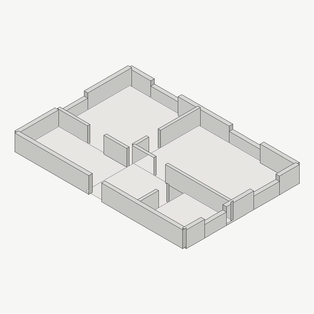
A 3D floor plan render — often called a doll's-house or isometric view — is a cutaway view of a plan seen from above at an angle, with walls extruded to a partial height so the interior stays visible. It is the fastest way to make a layout legible to a non-technical buyer, which is why it dominates off-plan sales material, competition boards and multi-unit portfolios.
The three ways firms produce them
1. In-house 3D modelling
Full control and full fidelity, but it consumes your team's hours per unit type. For a tower with a dozen layout variants, this is days of work that does not advance the design.
2. External render studios
High quality and high cost per image, with turnaround measured in days. Sensible for hero visuals; hard to justify across an entire floor-plate portfolio.
3. AI floor plan tools
Minutes instead of days — but most of them hand your plan to an image model and hope. The output looks plausible and quietly moves a door to the wrong wall.
Why most AI renders drift from the plan
An image model has no concept of a wall centreline or a door hosted on a specific wall segment. It reproduces the visual character of a floor plan, not its geometry. Typical failures to look for:
- Doors relocated to a different wall, or swinging into a wall.
- Windows invented on interior partitions.
- Rooms merged, split, or resized relative to each other.
- Wall thickness rendered inconsistently across the same plan.
Start from CAD if you can
The single biggest quality lever is the file you upload. A DXF or a vector PDF carries the real line work, so wall centrelines, opening positions and named blocks are parsed rather than guessed, and the scale can be read from the drawing's own units or its 1:100 note. A raster scan or a phone photo still works, but the geometry is then estimated from the page image — and the fidelity report says so.
- DXF exported from your CAD package — best.
- Vector PDF (plotted, not a screenshot).
- 300–400 DPI scan.
- Phone photo, taken square-on.
One unit or floor per file, title blocks and schedules cropped out, furniture and dimension layers dropped, walls as double lines. Millimetres are preferred.
Constructed geometry: a different pipeline
The alternative is to stop asking the model for geometry at all. Isoma reads the plan into a geometry model, validates it, builds the isometric scene itself, and only then lets AI apply materials and lighting:
- Grounding — walls, openings, rooms and scale are extracted from the drawing into a structured model.
- Validation — the model is checked against architectural invariants, with auto-repair for gaps, collinear walls and doors that need snapping to their host wall.
- Construction — walls are extruded at their true thickness and openings are cut at their exact position along the host wall, fixtures are placed where the drawing puts them, and the building's exterior envelope is applied — producing a real isometric scene.
- Approval — optionally the job stops here and shows you what it understood. Nothing is charged or styled until you approve the geometry.
- Styling — AI applies materials, lighting and furniture on top of that fixed structure.
- Verification — the styled render is compared back against the constructed geometry and scored. Renders that fail the check are retried from the original plan rather than delivered.
- 4K master — optional. The upscaled image is scored against the same geometry again and discarded if it drifted.
Keeping a whole building consistent
A portfolio problem is a consistency problem. In Isoma a building holds one exterior specification — facade finish and colour, window frames and glazing, balconies and railings, ground floor and landscape — plus one style anchor, and every unit type inherits both. That is applied to the constructed geometry itself rather than re-described in a prompt each time, and if you change the specification later you are shown which units go stale before anything is re-rendered.
What to check before a render goes to a client
- Every door appears on the same wall as in the source plan.
- Window count and position match per façade.
- Room adjacency and relative proportions are preserved.
- Circulation reads correctly — corridors and entries are where they should be.
A tool that gives you a fidelity score against your own plan turns that checklist from a manual review into a reported number.
Working at portfolio scale
For whole-building work the unit of production is not one image, it is a batch of layouts with consistent styling. Isoma handles up to 50 plans per batch across 7 interior styles, with Standard renders in about 1–3 minutes and Precision renders — geometry constructed from your plan — in roughly 2–4 minutes each. Precision renders can be taken to a 4K master for print.
Uploaded plans stay private and are never used to train models.
Try it on one of your own plans
Free credits on signup, no card required. Upload a plan and compare the constructed geometry against your drawing before you commit to anything.